
Objective 13: FPGA Programming - 2021 SANS Holiday Hack Challenge
In this one we learn what the heck an FPGA is and how to program one.
Play the 2021 SANS Holiday Hack Challenge
Objective
Write your first FPGA program to make a doll sing.
Hints
- There are FPGA enthusiast sites.
- There’s also an FPGA talk
Setup
We’re immediately presented with this screen:
Hello, students! In exercise #4, we continue our FPGA journey, documenting the creation of the sound chip for this holiday season’s new Kurse ‘em Out Karen doll. Our goal is to make the doll say its trademark phrase. But, as I always tell you in class, we must walk before we run.
Before the doll can say anything, we must first have it make noise. In this exercise you will design an FPGA module that creates a square wave tone at a variable frequency.
Creating a square wave output takes our clock signal (which is also a square wave) and uses a counter to divide the clock to match the desired frequency. One tricky problem that we’ll encounter is that Verilog (v1364-2005) doesn’t have a built-in mechanism to round real numbers to integers, so you’ll need to devise a means to do that correctly if you want your module to match frequencies accurately.
Good luck and always remember:
If $rtoi(real_no * 10) - ($rtoi(real_no) * 10) > 4, add 1
Exiting out of that, we’re presented with this screen:
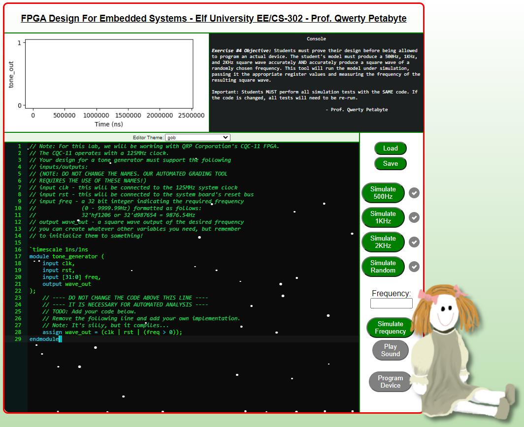
This is what it says in the upper right-hand corner:
Console
Exercise #4 Objective: Students must prove their design before being allowed to program an actual device. The student’s model must produce a 500Hz, 1KHz, and 2KHz square wave accurately AND accurately produce a square wave of a randomly chosen frequency. This tool will run the model under simulation, passing it the appropriate register values and measuring the frequency of the resulting square wave.
Important: Students MUST perform all simulation tests with the SAME code. If the code is changed, all tests will need to be re-run.
-Prof. Qwerty Petabyte
The starting code is this:
// Note: For this lab, we will be working with QRP Corporation's CQC-11 FPGA.
// The CQC-11 operates with a 125MHz clock.
// Your design for a tone generator must support the following
// inputs/outputs:
// (NOTE: DO NOT CHANGE THE NAMES. OUR AUTOMATED GRADING TOOL
// REQUIRES THE USE OF THESE NAMES!)
// input clk - this will be connected to the 125MHz system clock
// input rst - this will be connected to the system board's reset bus
// input freq - a 32 bit integer indicating the required frequency
//              (0 - 9999.99Hz) formatted as follows:
//              32'hf1206 or 32'd987654 = 9876.54Hz
// output wave_out - a square wave output of the desired frequency
// you can create whatever other variables you need, but remember
// to initialize them to something!

`timescale 1ns/1ns
module tone_generator (
    input clk,
    input rst,
    input [31:0] freq,
    output wave_out
);
    // ---- DO NOT CHANGE THE CODE ABOVE THIS LINE ----
    // ---- IT IS NECESSARY FOR AUTOMATED ANALYSIS ----
    // TODO: Add your code below.
    // Remove the following line and add your own implementation.
    // Note: It's silly, but it compiles...
    assign wave_out = (clk | rst | (freq > 0));
endmodule
The Talk
A couple of things to note from the FPGA talk:
- The frequency input is passed in as NNNNDD, specifying a frequency of NNNN.DD
- Ex. 234567 will be specified when requesting a 2345.67 Hz square wave
- Our output should be a square wave (alternating between 1 and 0) at the desired frequency
- Remember: a square wave has a 1/2 duty cycle, meaning it is set to HIGH for 1/2 of the cycle and LOW for 1/2 of the cycle.
There’s also some Verliog code in the talk that I’m going to replicate here:
module blink(
	input clock_100MHz, // 100 Mhz clock source on Basys 3 FPGA
	input reset, // reset
	output blinky
);
	reg [26:0] one_second_counter;
	reg blinker;
	assign blinky = blinker;

	always @(posedge clock_100MHz or posedge reset)
	begin
		if (reset==1)
			begin
				one_second_counter <= 0;
				blinker <= 0;
			end
		else
			begin
				if(one_second_counter >= 100000000)
					begin
						one_second_counter <= 0;
						blinker <= blinker ! 1`b1;
					end
				else
					one_second_counter <= one_second_counter + 1
			end
	end
endmodule
This code blinks an LED on for one second and off for one second (making a what is technically a 2Hz signal in total).
The Challenge
Rounding
Let’s deal with the problem of rounding first, since I have a pretty good idea of how to do that because of the hint in the initial splash screen.
if($rtoi(real_no * 10) - ($rtoi(real_no) * 10) > 4)
	rounded_no <= $rtoi(real_no) + 1
else
	rounded_no <= $rtoi(real_no)
The $rtoi function converts a real number (i.e. a decimal / float) to an integer by truncation.
It’s easiest to explain this code through an example: Let’s see how we can use this code to round the number 13.54.
$rtoi(13.54 * 10) = $rtoi(135.4) = 135
AND
($rtoi(13.54) * 10) = 13 * 10 = 130

THEREFORE
$rtoi(13.54 * 10) - ($rtoi(13.54) * 10) = 135 - 130 = 5
As you can see, this way we can obtain just the first decimal place of any real number. If that first decimal place is 5 or above, we truncate the number and add one. Otherwise we just truncate the number.
Using the Blinker Code
We’ll use the blinker code from the talk as a framework for our code
`timescale 1ns/1ns
module tone_generator (
    input clk,
    input rst,
    input [31:0] freq,
    output wave_out
);
    // ---- DO NOT CHANGE THE CODE ABOVE THIS LINE ----
    // ---- IT IS NECESSARY FOR AUTOMATED ANALYSIS ----

	reg [31:0] counter;
	reg wav_o;
	assign wave_out = wav_o;

	always @(posedge clk or posedge rst)
	begin
		if (rst==1)
			begin
				counter <= 0;
				wav_o <= 0;
			end
		else
			begin
				if(counter >= ???????)
					begin
						counter <= 0; //NOTE: There is a bug here that gets changed later. Keeping it as-is here to be true to the blinker code.
						wav_o <= wav_o ^ 1'b1; //flips the value of wav_o (i.e. from a one to a zero or a zero to a one)
					end
				else
					counter <= counter + 1
			end
	end
endmodule
Finding Clock Cycles per Flip
The main thing we need to figure out is this: how do we know when to flip the counter? Before we start considering the code, let’s consider the math.
The Math
The first thing to understand is that frequency is measured in Hertz (Hz), which is just the number of full cycles something completes per second.
The first bit of math we have to do is figure out the actual frequency desired from the format it’s given to us:
$$ f_{real} = freq/100 $$
Then, because we need to flip the value of wav_o 2 times per cycle, we multiply that by two:
$$ f_{flips}=f_{real}*2 $$
Therefore:
$$ f_{flips}=2*freq/100=freq/50 $$
Now we have to convert our desired flips per second to clockcycles per flip:
$$ \frac{1}{\frac{freq}{50}} \frac{second}{flips} * \frac{125,000,000}{1}\frac{clockcycles}{second} = \frac{125,000,000}{\frac{freq}{50}}\frac{clockcycles}{flips} $$
So in order to find the number of clock cycles in-between flips, all we need to do is divide the clock speed (125,000,000) by the given frequency over 50 and then round it to the nearest whole number.
The Code
integer clockspeed;
real cpf_real;
integer cpf;

initial begin
	clockspeed = 125000000;
	cpf_real = 0.0;
	cpf = 0;
end


//find real number of clockcycles per flip
cpf_real <= clockspeed / (freq / 50);

//round clockcycles per flip
if($rtoi(cpf_real * 10) - ($rtoi(cpf_real) * 10) > 4)
	cpf <= $rtoi(cpf_real) + 1;
else
	cpf <= $rtoi(cpf_real);
Putting it Together
`timescale 1ns/1ns
module tone_generator (
    input clk,
    input rst,
    input [31:0] freq,
    output wave_out
);
    // ---- DO NOT CHANGE THE CODE ABOVE THIS LINE ----
    // ---- IT IS NECESSARY FOR AUTOMATED ANALYSIS ----

	//declare our variables
	integer clockspeed;
	integer cpf; // cpf stands for clockcycles per flip
	real cpf_real;
	reg [31:0] counter;
	reg wav_o;
	assign wave_out = wav_o;

	//Initialize our variables
	initial begin
	    clockspeed = 125000000;
	    cpf_real = 0.0;
    	cpf = 0;
    end

	always @(posedge clk or posedge rst)
	begin
		if (rst==1)
			begin

				//find real number of clockcycles per flip
				cpf_real <= clockspeed / (freq / 50);

				//round clockcycles per flip
				if($rtoi(cpf_real * 10) - ($rtoi(cpf_real) * 10) > 4)
					cpf <= $rtoi(cpf_real) + 1;
				else
					cpf <= $rtoi(cpf_real);

				//re-initialize the counter and output
				counter <= 0;
				wav_o <= 0;

			end
		else
			begin
				if(counter >= cpf)
					begin
						counter <= 1;
						wav_o <= wav_o ^ 1'b1; //flips the value of wav_o (i.e. from a one to a zero or a zero to a one)
					end
				else
					counter <= counter + 1;
			end
	end
endmodule
Note: There was a catch in the blinker code that caused it to be very slightly off. Because of the way the reset function takes up one clock cycle in this code, cpf needs to set to zero on each reset, but should be set to one (not zero) every time wav_o is flipped. That way we don’t over-count any of the clock cycles.
Testing It
Now all we have to do is run this code against the 500 Hz, 1K Hz, and 2K Hz tests on the right-hand side of the screen. Once it passes all of the tests, the “Program Device” button should turn green. Click on that and you’re done!